 DrivePro Auto
DrivePro Auto
DrivePro Auto
Metal fatigue in OTR wheel rims can develop quietly beneath dirt, paint, and repeated heavy loading. A rim may look serviceable while microscopic cracks grow around bolt holes, valve openings, welds, and flange edges. The key question is: What are the signs of metal fatigue in OTR wheel rims? Common clues include hairline cracking, rust trails, polished crack edges, uneven bead seating, rim distortion, repeated air loss, and unusual vibration during operation.
OTR wheel-safety specialist Gary A. Mullen explains, “A small crack is not a cosmetic defect; it is evidence that the rim has begun losing its safety margin.” His warning reflects practical field experience. Inspectors should clean the rim carefully, use strong lighting, and compare suspicious areas with manufacturer limits. Dye penetrant or magnetic-particle testing may reveal damage that eyesight misses. Never rely on repainting or hammering a damaged rim into shape.
The details matter. A crack beside a bolt hole may resemble a scratch. A dark line beneath the flange may be old paint—or an active fracture. Service history also matters, especially with overloaded equipment, severe impacts, corrosion, and frequent tire changes. Experienced technicians should remove questionable assemblies from service and follow the rim manufacturer’s procedures.
Not every mark proves fatigue. That uncertainty deserves respect. Still, delaying inspection can turn a manageable defect into a violent rim failure. This guide examines visible warning signs, inspection methods, and practical decisions for safer OTR wheel maintenance.
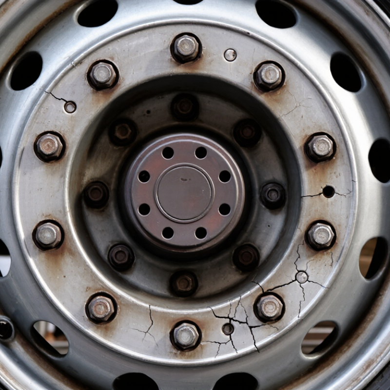
How to Identify Metal Fatigue in OTR Wheel Rims 2026?
Understanding Metal Fatigue in OTR Wheel Rims
Metal fatigue develops when an OTR wheel rim receives repeated loading, unloading, braking, and impact cycles. The damage may begin as a tiny crack near the bolt holes, valve opening, bead seat, or weld area. SAE J267 describes repeated radial and cornering-load tests for heavy-duty wheels. These tests reflect a key reality: one overload may bend a rim, but thousands of smaller cycles can create hidden failure.
Field inspection should start with cleaning. Dirt can hide a dark line only a few millimeters long. Look for fresh metal dust, rust trails, distorted flange edges, and uneven tire seating. Dye penetrant testing can expose surface cracks after visual inspection. ASTM E1417/E1417M provides a recognized method for liquid penetrant examination. Ultrasonic testing may detect deeper flaws, although results depend heavily on operator skill. That part is often underestimated.
Tips: Record rim hours, tire pressure, payload, and impact events. Compare photographs during every planned inspection. Remove a rim from service when cracks, severe deformation, or repeated air loss appear. Do not grind a suspected crack away and call the repair complete. It may return.
The 2024 Mine Safety and Health Administration injury data continues to show that mobile equipment remains a major safety concern in mining environments. The report does not isolate rim fatigue, but it supports disciplined inspection around heavy mobile machinery. A practical weakness remains: maintenance records are sometimes incomplete. Without cycle history, fatigue assessment becomes educated guessing, not certainty.
| Inspection Dimension | Typical Rim Location | Observable Fatigue Indicators | Recommended Detection Method | Risk Level | Recommended Response |
|---|---|---|---|---|---|
| Surface crack initiation | Flange edges, bead seat transitions, gutter sections and sharp geometric changes | Fine linear marks, branching cracks, repeated dark lines after cleaning, or cracks that follow a weld toe or forming radius | Clean and dry the rim; use bright lighting, a close visual inspection and a suitable dye penetrant or magnetic-particle examination where applicable | High | Remove from service until assessed. Do not grind, weld or drill a suspected fatigue crack without an approved repair procedure |
| Crack growth pattern | Disc-to-rim welds, circumferential welds and areas around the wheel center | Crack length increases between inspections, crack branches appear, or a crack travels around the circumference or through a weld heat-affected zone | Record crack location and length with photographs; repeat inspection using the same reference points; use surface or volumetric NDT when required | High | Quarantine the wheel and obtain a competent engineering disposition. Any progression is a strong rejection or replacement signal |
| Weld-toe fatigue | Disc-to-rim welds, reinforcement welds and welded attachments | Toe undercut, porosity exposed by wear, irregular weld profile, corrosion staining, or a crack parallel or transverse to the weld | Visual inspection followed by magnetic-particle testing for suitable ferromagnetic steel components; ultrasonic testing may be used for subsurface indications | High | Stop operation if cracking is confirmed. Repair is acceptable only when specifically permitted, engineered and inspected after repair |
| Flange and bead-seat deformation | Flange lip, bead seat, lock-ring groove and side-ring contact surfaces | Flattened or rolled flange, local dents, uneven bead seating, metal displacement, or a visible change in the rim profile | Compare the rim with approved dimensional limits; use a straightedge, profile gauge or calibrated measurement equipment | High | Deflate and isolate the assembly using safe procedures. Do not attempt to straighten a pressurized or mounted rim |
| Fastener-hole fatigue | Wheel bolt holes, stud seats and mounting-face transitions | Elliptical holes, fretting marks, raised metal, radial cracks, loose fasteners or repeated loss of torque | Visual and dimensional inspection; check runout and mounting-face condition; use magnetic-particle testing when appropriate | High | Do not reuse a wheel with cracks, excessive hole elongation or damaged seating surfaces. Investigate torque, fitment and hub condition |
| Valve-hole fatigue | Valve-hole edge and the surrounding rim material | Radial cracking, fretting, corrosion around the valve stem, distorted edges or repeated air leakage | Clean the area and inspect under magnification; use dye penetrant or magnetic-particle testing when the material and procedure allow | Medium–High | Remove from service if a crack is present. Replace damaged valve hardware and verify that the valve does not contact the tire or bead area |
| Corrosion-assisted fatigue | Inner rim surfaces, bead seats, weld areas, drain points and regions exposed to moisture or chemicals | Pitting, layered scale, paint blisters, rust lines emerging from pits, or local section loss near a stress concentration | Remove loose corrosion without damaging the base metal; inspect thickness and surface condition using approved NDT or calibrated measurement tools | Medium–High | Assess remaining section and crack indications. Replace when corrosion has reduced structural integrity or limits cannot be verified |
| Impact-related fatigue | Flanges, side rings, bead seats, disc areas and rim edges | Fresh dents, chipped coating, witness marks, localized buckling or a crack extending from an impact point | Inspect immediately after severe impact, tire damage or sudden air loss; check radial and lateral runout against approved limits | High | Deflate and remove the assembly from service for a full inspection. Impact damage can initiate cracks that are not visible from one side |
| Thermal fatigue | Brake-side disc areas, welds, bead seats and regions exposed to repeated heating and cooling | Heat discoloration, coating loss, radial cracks, distortion, or cracking that follows a weld or thickness transition | Review operating history and inspect after overheating events; use visual inspection and suitable surface NDT after the rim has cooled | Medium–High | Investigate brake drag, overload and cooling conditions. Replace or engineer-assess rims with heat distortion or confirmed cracks |
| Runout and vibration trend | Entire wheel assembly, especially the rim radial and lateral profile | Progressively increasing vibration, uneven tire wear, steering shake, or runout that worsens after service | Measure radial and lateral runout with calibrated equipment; compare results with the applicable wheel and vehicle limits | Medium | Separate tire, hub, mounting and rim causes. Do not treat balancing as a cure for structural cracks or permanent deformation |
| Load-cycle and service-history review | All structural areas, with emphasis on high-cycle stress zones | Repeated overloads, severe haul-road impacts, chronic underinflation, excessive heat, frequent retorquing or a high number of operating cycles | Review maintenance records, payload history, tire pressure data, impact events and previous repairs; compare inspection intervals with duty severity | Medium | Increase inspection frequency when duty severity rises. A service-history review complements, but does not replace, NDT |
| Post-repair verification | Any repaired weld, heated area, machined surface or replaced rim component | New crack indications, weld discontinuities, dimensional changes, distortion or incomplete documentation | Verify repair records, material compatibility, dimensional conformity and required NDT results before installation | High | Do not return the rim to service without documented acceptance by a qualified person and confirmation of required service limits |
Repeated loading, unloading, braking, impacts, and heat cycles can weaken the metal. One overload may bend it. Thousands of smaller cycles can create hidden cracks.
Inspect bolt holes, valve openings, bead seats, welds, and flange edges. Cracks often begin near sharp corners. Check for rust trails, polished metal, fresh metal dust, and distorted edges.
Yes. Dirt, paint, and corrosion may hide a short crack. Clean the rim first. Use bright, angled lighting and a small inspection mirror.
Repeated air loss, vibration, uneven tire seating, and a rim that runs unevenly need attention. Blue or brown marks may indicate excessive heat. Stretched bolt holes are also concerning.
No. Visual checks can miss deeper or very small flaws. Dye penetrant or magnetic-particle testing can reveal surface cracks. Ultrasonic testing may find deeper damage, but operator skill matters.
Record rim hours, tire pressure, payload, torque readings, and impact events. Photograph suspicious areas with a measurement scale. Records may be incomplete. That weakens the assessment.
Remove it immediately after finding a confirmed crack, severe distortion, deep corrosion, or repeated air loss. Do not keep using it for another shift. Uncertainty alone may justify further testing.
Do not grind, weld, heat, drill, or straighten a cracked rim without engineering approval. These actions can hide damage or change the metal’s strength. Replacement is often safer when limits are unclear.
Metal fatigue in OTR wheel rims develops through repeated heavy loads, flexing, impacts, and stress cycles, gradually weakening the metal even when no major accident has occurred. What are the signs of metal fatigue in OTR wheel rims? Common warning signs include fine hairline cracks around bolt holes, bead seats, welds, valve openings, and other high-stress areas, as well as peeling paint, rust lines, distorted rim components, or recurring air loss. Early detection is essential because small cracks can expand without obvious surface deformation.
A step-by-step inspection should begin with cleaning the rim, checking its overall shape, and examining critical areas under strong lighting. Non-destructive testing may help reveal cracks that are difficult to see. Fatigue cracks typically appear as progressive, branching lines, while impact damage may cause dents or sudden deformation. Any suspected defect should be documented and assessed by a qualified professional. Depending on its location and severity, the rim may require controlled repair or complete replacement. Continuing to use a damaged rim can increase the risk of air loss, component separation, and serious equipment failure.
